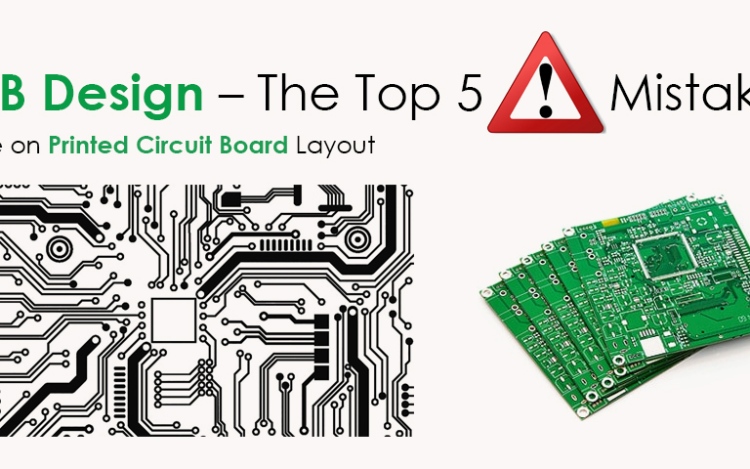
The following are a couple of configuration mistakes referenced, which a PCB maker ought to stay away from while structuring one. Printed Circuit Board has always been given utmost importance and the mistakes taking place are serious glitches which should be avoided through following ways. Boar
Over confused structures:
The fundamental working philosophy behind the Printed Circuit Board design enables the producer to create a printed circuit board (PCBs) in the most prudent and least demanding way. Be that as it may, an overcomplicating configuration may cause a few issues like a schematic awkwardness.
It may influence the believability and profitability of a PCB creator. Thus, a creator must concentrate on the adequacy of the structure and should improve it to maintain a strategic distance from plan mistakes.
Incorrect Format Of The Reception Apparatus In The Remote Structure:
If the circuit board is utilizing remote innovation, at that point, a right radio wire design is significant. The impedance of the handset and the receiving wire must be coordinated to guarantee the most extreme power move.
A legitimate transmission line is expected to associate the handset and the receiving wire. For the most part, the transmission line is made with 50-ohm impedance for the most significant power move inside the reception apparatus.
Fabricators must make an exceptional note on introducing the receiving wire accurately to give a viable circuit board structure.
Limiting Slithers:
Slithers are undissolved copper lumps that may adhere to the circuit board during the substance carving process. These crawls may cause short circuits and a few other assembling disappointments.
A PCB planner ought to consistently guarantee that the base copper width is over the producer’s prerequisite. This limits crawls, and produce appropriately working for circuit sheets.
Landing Pattern Errors:
Libraries of electronic segments are accessible in the PCB plan programming bundles. Schematic image and printed circuit boards landing design for every section is a couple of parts incorporated into the library.
The schematic image and the arrival design are to be drawn physically if the segments used outside of the libraries in the PCB software configuration bundle. It may expand the likelihood of blunders.
Decoupling capacitors:
The decoupling capacitors give stable voltage to parts on the printed circuit board. They are set nearer to the stick to guarantee a steady voltage. The following driving the inventory rail must go through the decoupling capacitors before arriving at the pin.
If this occurs, at that point, stable voltages can be given. Henceforth, the PCB architects need to use the decoupling capacitors adequately.
As talked about, flexible printed circuits format configuration requires vigorous exactness and extraordinary innovative abilities. Mistakes in PCB design can prompt immense misfortunes. Along these lines, controlled PCB configuration is a significant check to keep any low-quality items from arriving at the market.
It is safe to say that you are attempting to fabricate your PCB? Indeed, it is, in every case, better to move toward an industry master with a significant encounter —https://www.fpcdesign.com/ is one of the rumored PCB makers offering a tremendous scope of PCB arrangements.


